
For the latest in our ongoing series of post where I overthink simple questions, I'd like to present the longest single continuous experiment in Uncertain Principles history, which took six and a half hours yesterday. All to answer the question in the post title.
This may seem like a waste, given that I could download a spec sheet, but it was a simple extension of yesterday's lab. I'm teaching E&M this term, and we're wrapping up the circuits portion of the class. Yesterday's lab was about the discharging of capacitors.
This is one of those concepts that sneaks in largely as a way to introduce simple differential equations. A capacitor is a device for storing charge, and will act as a current source for a short time, until the charge is exhausted. The current coming out changes very rapidly, though, and the change is proportional to the current flowing, so a tiny bit of calculus shows that you have an exponential decay:
$latex I(t) = I(t=0)e^{-t/RC} $
The C is the capacitance of the thing you're using to store charge, and the R is the resistance of the load the current is flowing through. Given those, you can easily calculate whatever you like about the capacitor's behavior.
In the lab we do with our intro E&M class, we have students connect a big-- 0.01 F-- capacitor in series with a variable resistor, and measure the decay with a voltage probe connected to a PASCO computer interface. By measuring the time required for the voltage to decay, they can get an experimental value of RC, and compare this to the values they read off the variable resistor and the capacitor. This is, of course, the worst sort of "confirm what we did in class" lab, a fact that I never remember until I'm setting it up right before class...
Anyway, as I was setting this up, early Thursday morning, it occurred to me that I could turn this around and measure the computer interface. That is, when we set this up, there are really two elements connected to the capacitor: the resistor that we're using for the experimental load, and the computer interface. Now, as we tell students in class, an ideal voltage probe has infinite resistance, so it doesn't perturb the system in any way, but electronics supply firms tend to be a bit short on infinite resistance components. At one point in grad school, we needed a giga-ohm resistor for something, and we had to handle it with latex gloves, lest the oil from our fingers provide a lower-resistance channel for current to flow around the outside of the resistor.
So, the PASCO box is going to have some finite resistance. Which means, if I disconnect the variable resistor from the circuit, so the capacitor is only connected to the computer, and nothing else, it will discharge through whatever the internal resistance of the voltage sensor is. Measuring that decay will give an RC value, and since I know the capacitance already, I can use that to determine R for the computer interface.
And so, that's what I did: I set up the three copies of the apparatus needed for the class, and also a fourth, where I charged up the capacitor and let it discharge through the computer. For kid-related reasons, I was doing this at 8am, so by the time my 10:55 lab rolled around, it had piled up quite a bit of data. I let it run through the colloquium talk at lunch, until I went home for the day around 2:30. The full data set looks like this:
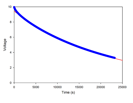 The discharge of a capacitor through the PASCO interface. Blue points are data, red line is a single exponential fit.
The fat blue line is not, in fact a line, but 11,000 data points (I had it recording one point every 2s). The red line is a fit to an exponential decay function. You can see that this misses the data a bit at the start; if I zoom in on the first 1000s of data, you can see it more clearly.
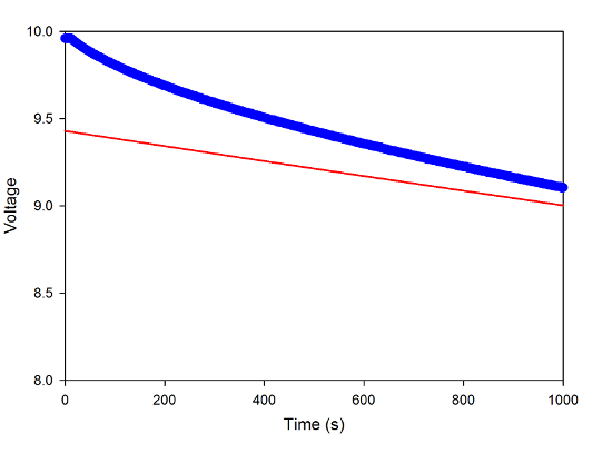 Zooming in on the first 1000s where the single-exponential fit misses.
That's a little surprising. It looks very much like there's a second decay happening at a much faster rate. But that's something easy to fit with real data analysis software, so here's a double-exponential fit:
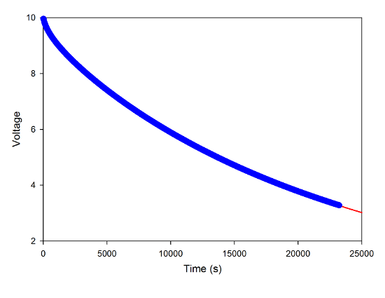 The decay data with a double-exponential fit.
 Zooming in on the first 1000s of the data, with the double-exponential fit.
This does much better, though it still misses some stuff at the beginning. I'm really not sure what's going on, there.
Anyway, it doesn't end up making much difference one way or the other. There's so much data in the later part that the longer decay constant is very nearly the same for the two cases, around 22,000 seconds. For the known value of the capacitor, that gives an input resistance for the computer of 2.2 MΩ.
How does that compare to the PASCO specs? It's off by a factor of two-- they claim 1MΩ input impedance. I don't entirely understand this, either-- there are, of course, the resistance and capacitance of the connectors and switch and so on to think about, but the values here are huge, way bigger than I would expect for miscellaneous connector issues. I suppose it could just be a mistake in the specs, but then I would think that would throw off all their voltage measurements, which are otherwise pretty accurate, so I don't think that's it.
Which just goes to show that even stupid, simple experiments can produce some mysteries. I could imagine a couple of things I might try to sort this out, but at six and a half hours per trial? Yeah, not so much... So we'll just leave that out there, unanswered, unless one of the several electrical engineers who read this want to comment pointing out the stupid and obvious thing I'm missing.
Is that an electrolytic capacitor? If so, it acts as a battery, too. One would expect its initial and final behaviors to deviate from simple capacitance expectations. The start would be a big gulp. The end would tail off too slowly. Big electrolytics are commonly stored bridged by a high resistance to prevent self-recharging.
The capacitor is almost certainly electrolytic if it has that capacitance and that size--a few microfarads is already a pretty big capacitance, and you're dealing with something three orders of magnitude larger. I'm not an electrical engineer, so I don't know how that will deviate from an ideal capacitor, but I'm not surprised that it does. It will have some internal resistance as well, and that could be throwing off your calculation. Check the spec sheet on the capacitor.
Typically voltage measurement instruments are specified "input impedance not less than", not to an exact value. Low-impedance things, such as circuit analyzers, do get much closer to their rated specs, but there it is a matter of matching, not of not loading the device under test.
While you're looking at the capacitor spec sheet, you should also check the tolerance; big electrolytics tend to be within a rather large range. The "known value of the capacitance" may not be known very well.
The capacitors are certainly electrolytic, because I've had students wire one up wrong and blow it up, spraying oil all over their table. Stank like hell.
That probably accounts for the odd behavior at start and end. I wouldn't think the internal resistance is to blame, because it seems like that would end up in parallel with the load, not in series, which would lead to a lower effective resistance, where what I measure is larger than the spec.
The capacitor value is known not just because it's printed on the capacitor, but because the RC values calculated using that value in the regular lab are generally within a few percent of the measured values from the decay time. They might be off by a small amount, but unless the variable resistor boxes are off in the other direction by nearly the same amount, it can't be a big difference.
I guess it could be the "not less than" thing, if they set the calibration using the actual value rather than the spec.
Could it be the difference between resistance and impedance?
A loudspeaker will have a DC resistance of 8 ohms but the impedance varies a lot over the audio spectrum. Speaker cabinets are modeled by LCR circuits (Thiele/Small). Perhaps the spec should be "not less than" over a frequency range.
I'm wondering if you charged the capacitor for only a short time rather than leaving to "soak" charge for at least twenty minutes. Dielectric absorption is most often associated with the buildup of voltage after a capacitor has been fully discharged, however, it also has the opposite effect after charging.
Have a look the diagram: Circuit model for explaining a time-delayed voltage build-up by parallel RC-timers
http://en.wikipedia.org/wiki/Dielectric_absorption
This model seems to explain why your double exponential was required, but still didn't quite fit the data.
Try measuring it directly with an electrometer. Keithley rules